(Page 2)
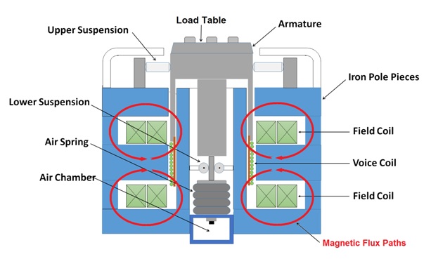
Figure 3: Schematic representation of a Sentek Dynamics electromagnetic shaker.
Figure 3 provides a schematic representation of a typical shaker. The cylindrical armature is the shaker’s moving structure. It consists of an upper load table to which the DUT is bolted and a lower coil form. The armature sits on a soft air spring which provides a soft vertical spring rate for the internal load support system. Pressure within the air spring may be adjusted to support and vertically center any payload up to the Maximum Static Payload. The armature is held concentric with the shaker body by an Upper Suspension and Lower Suspension. The upper suspension is typically a series of radially dispersed and elastically retained rigid rolling-contact “dog bone” shaped guides. The lower suspension is a set of four rollers bearing on a square shaft. These suspension elements stiffly restrain the armature from rocking, twisting or moving laterally. They allow it to move freely in the axial (vertical) direction against the soft spring rate of the air spring. The Effective Armature Mass is the mass of the armature and the additional effective inertia of the suspension elements that move with it. The Armature Diameter describes the maximum diameter of the load table.
A copper wire Voice Coil is wound about the bottom portion of the armature. This coil sits in a strong (static) radial magnetic flux path produced by two DC-excited Field Coils. When a current is passed through the voice coil, a corresponding axial force acts upon the armature. This force is proportional to the voice coil current, to the length of wire in the magnetic field and to the magnetic flux density (in turn proportional to the field coil DC current). The system Amplifier drives both coils. It provides a DC current to the field coils, providing a strong static radial magnetic flux. It provides an AC current to the voice coil in proportion to a Drive input signal provided by the Vibration Controller. The net result is that the armature moves up and down in response to the Drive command provided by the controller. The shaker acts like a gigantic ruggedized loudspeaker.
The electrodynamic shaker reflects strong interplay of electrical and mechanical dynamics. The mechanical system is excited by a force proportional to electrical current, while the electrical circuit is excited by a generated voltage (back-EMF) proportional to the mechanical velocity of the voice coil. The amplifier drives the electrical circuit providing an external voltage, e, and driving current, I, as shown in Figure 4.

Figure 4: The mechanical and electrical actions of a shaker are cross-coupled.

Figure 5: The mode shapes of the three dominant shaker resonances.
Figure 4 provides some insight into the physics that limit a shaker’s performance. In the lumped-mass model on the left, the armature is represented by the two elastically coupled masses MT (the load table) and MC (the coil form). The DUT is represented by appended mass, MD. The shaker body is represented by MB . The spring rate KS and the damping rate CS represent the air spring supporting the armature and the DUT. The stiffness KC and (very low) damping rate CC represent the coil-connecting structure of the armature. The stiffness KB and damping rate CB model the vibration isolators that support the body of the shaker. R represents the voice coil resistance and L represents its inductance. The constants k1 and k2 reflect the electromechanical coupling (current-to-force and velocity-to-voltage).
Three modes of vibration dominate the mechanical signature and reflect in the electrical signature. The mode shapes of these three modes are shown in Figure 5. At very low frequency (2-3 Hz), the compliant isolation mounts allow the entire shaker to translate as a rigid body with almost no relative motion between its components. This deformation shape is termed the Isolation Mode. The Suspension Mode occurs next, near the lower end of the shaker’s Frequency Range. In this mode, the table and coil move together as a rigid body relative to the shaker body. Motion in this mode is limited by the design Stroke of the machine. When the shaker is properly loaded and centered in its stroke, the frequency of the suspension resonance is (essentially) constant, regardless of the payload attached to the load table. The air spring pressure is adjusted manually against an armature-height alignment gauge or automatically (if equipped with automatic armature centering) by adding shop air or venting after mounting a new DUT. Air is added to support the mass of the payload, that is the air spring takes on a supporting preload to balance the added mass. However the air spring also stiffens in proportion to its internal pressure. Since the suspension stiffness tracks the payload mass, the suspension resonance frequency remains unchanged. At or beyond the high frequency limit of operation, the (undesired) Armature Resonance is encountered. Here, the coil moves out-of-phase with the drive table and the elastic armature structure is stressed as a result. Excessive excitation in this mode can seriously damage the armature.