(Page 7)
Step 1 – Classical Shock Testing
Controlled electrodynamic shakers have become the preferred test platform for modest shock tests. While drop-test (and other) facilities remain necessary for the simulation of extreme shock pulses, the controlled shaker has proven very cost effective for more routine product qualification and seismic evaluation work. Our modern shaker controllers do an outstanding job of reproducing desired transient pulses safely, reliably and repeatedly. Their use saves the enormous time of designing and iteratively using mechanical drop-targets to provide a required shock profile. One now merely keys in or selects the desired acceleration-versus-time shock profile and runs the test.
However, an electrodynamic shaker presents some physical barriers to shock testing. These machines have a limited range of displacement (stroke) and exhibit velocity limits that cannot be exceeded without loss of control. The shaker controller compensates for these shortcomings by employing a process termed compensation.
Shock test profiles are typically described by an acceleration-versus-time history of a few milliseconds duration. Certain shapes Illustrated in Figure 16 have evolved as the Classical Shock library. These basic pulse forms stem from prior drop-testing where the test object starts in free-fall and collides with a target whose elastic and crush properties determine the test acceleration profile. The resulting pulse shapes are almost invariably unipolar as displacement and velocity were not considerations in their development. When these same profiles are run on a shaker, velocity and displacement are the primary concern.
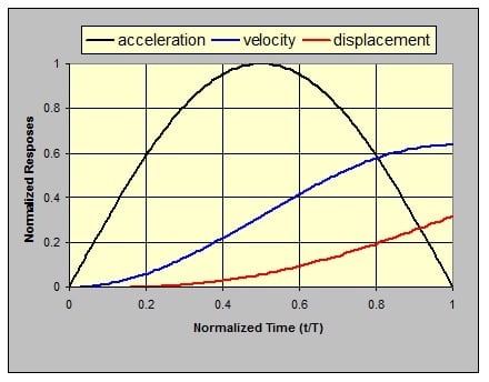
Consider the classic half-sine acceleration shock pulse shown in Figure 17. Since the acceleration is solely in the positive direction, the velocity at the pulse’s conclusion is positive and the test object continues to move at this velocity even though the acceleration has returned to zero. The test object has displaced during the shock pulse and will continue to displace at constant velocity until arrested by some barrier. Without smarter intervention, the stroke limits of a shaker could provide this barrier with likely expensive and dangerous results.
Figure 16: The Classic Shock pulse shapes.
Figure 17: Normalized responses to a half-sine acceleration pulse.
Black - acceleration/A, blue - velocity/AT, red – displacement
You will note that the motional responses of Figure 17 were presented in normalized form. Time was divided by the pulse duration, T, acceleration was divided by the peak acceleration, A, velocity was divided by AT and displacement by A2. These normalizations are industry-standards, allowing an acceleration pulse and its integrals to be easily over-plotted within a reasonable graphic range, without concern for the peak value of the pulse or its duration or the system of measurement units employed.
A shaker can only operate over a limited range of displacement, its stroke. Within this range it can only operate in a controlled fashion if its velocity limit is not exceeded. Companion amplifier voltage limits determine the maximum controlled velocity of an electrodynamic shaker. Hence, a shock-test can only be run if the resulting displacement falls within the shaker’s stroke range with peak velocity within system limits. Further, as a matter of practicality, the test must start from conditions of zero acceleration, velocity and displacement and return to this state at the conclusion. This is accomplished by adding additional compensation pulses of small-amplitude to the desired test profile.
The compensation pulses can be applied before or after the desired test pulse. In general, two pulses of opposite sign are required to cause the displacement, velocity and acceleration to start from and return to zero amplitude. The compensation pulses may be of the same shape as the test pulse or they can be of a very different shape (or shapes). Compensation pulse height is normally chosen to be a low value within the allowable tolerances of the chosen classical pulse. The two compensation pulses may be of different amplitudes. In general, a lower amplitude compensation pulse must be of longer duration. Figure 18 illustrates compensating a half-sine pulse with two rectangular pulses, each with amplitude equal to 20% of the half-sine’s amplitude.


