
Figure 23: A head expander fitted to the armature’s load table increases the mounting area.
(Page 9)
Step 2 – Device Specifications
Each candidate test object presents a new series of practical mechanical problems. First, the DUT must be firmly bolted to the shaker. However, you must assure that the center-of-gravity (CG) of the payload is directly over the center of the shaker to avoid stressing and damaging the shaker’s suspension. In some cases this results in offsetting the DUT’s mounting base from the shaker table’s center. In all cases you will need to position tapped holes to receive the hold-down bolts. This often translates into an adaptor plate with tapped holes to mount the DUT and through holes aligning with the tapped holes on the shaker’s load table. The adaptor is bolted to the shaker and then the DUT is bolted to the adaptor. Never drill and tap the load table of your shaker!
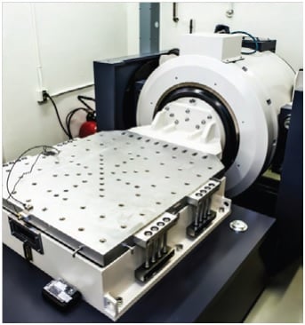
Figure 24: A slip table driven by a shaker through a driver bar is used for horizontal shake tests.
While a collection of clamps, hold-down bars and threaded rods may serve to mount a specimen for a one-off or experimental shake, anything that is routinely tested deserves its own adaptor. Proper mounting adapters assure the DUT is secured to the shaker in exactly the same way every time the test is run. Permanently mark or label each adaptor and bag and store the necessary mounting fasteners with it. Know the exact weight of each adapter set.
Sometimes the mounting base of a test specimen may too big to sit securely on the shaker with its CG centered. The solution to this problem may be a head expander such as that shown in Figure 23. Sentek Dynamics offers a wide range of standard head expanders to fit any of our shaker armatures. Aluminum and magnesium head expanders are available with square or round platforms in sizes from 300 mm (11.8 inch) to 1500 mm (59.1 inch). Custom head expanders (and custom adaptors and fixtures) can also be provided. Know the weight of each head expander and its table-mounting fasteners. Store these components together.
A device is often tested in multiple directions (multi-axis testing). If the device is small and light enough, a custom fixture may be built to hold and test multiple DUTs simultaneously. If the specification calls for the same test profile in each axis, the fixture can be designed to hold (multiples of) one DUT with its X-axis up, one with its Y-axis up and one with its Z-axis up. Should the specification call for a different profile in each axis, a different fixture holding multiple specimens may be required for each axis. Again, permanently mark each adaptor and store it with its required mounting fasteners – know the mass of each such fixture set.
In most cases, a small DUT can be rotated to align a desired test axis with the vertical. However, this may not always be true. If the DUT must be subjected to multi-axis shaking, but it cannot be laid on its side, you require a slip table. As shown in Figure 24, this is simply a horizontal table floated on an oil film excited by a shaker rotated to the horizontal and fitted with a driver bar. This rig is used to perform the X and Y-axis horizontal shakes. The Z-Axis is most probably done by remounting the DUT on the shaker after it is re-oriented to the vertical. Know the moving-mass of your slip table and the mass of your driver bar and all its fasteners.
In short, your analysis of the device under test (DUT) should reveal the mass that must be driven by the shaker in every test configuration required. This includes any adaptors, head expanders, slip tables, driver bars and fasteners required. For every axis (or other variation that must be driven), know the total mass that will be driven by the shaker.
Step 3 – Shaker Specifications
Verify that the total moving mass (for a vertical shake) identified in step 2 is less than the maximum static payload of a trial shaker. Add the shaker’s effective armature mass to the total moving mass determined in step 2. Multiply this total by the acceleration determined in step 1. The resulting peak force (F=ma) must be less than the Peak Sine Force rating of the shaker for a sine test and less than the Peak Shock force rating for a classical shock test. For a random test multiply the total moving mass by the computed RMS acceleration and verify the result is less than the shaker’s RMS Random Force rating. Verify that the shaker’s Frequency Range exceeds that determined for the test in step 1. Verify that the peak velocity required for the test is less than the Peak Velocity of the shaker. Be absolutely certain that the peak-to-peak displacement determined necessary for the test is less than the de-rated Maximum Displacement (Stroke) of the shaker. If all of these requirements are met, the shaker is suitable to run the test in question with the specified DUT and fixture payload.
If multiple benchmark tests must be met, some shaker iteration will likely be required. It will be necessary to select a shaker with the highest force rating and longest stroke required by all tests investigated. With an eye to your future, respect the old saw, “You can never own too much stroke!” Be aware that stroke and force ratings affect system price directly. Also be aware that owning insufficient shaker can cause you no end of grief.