Introduction
Earthquake testing is a crucial process that is used to determine the seismic performance of a structure. The utilization of a physical testing method helps users better understand the complexity involved in earthquake forces. A shaker table is typically used to execute a physical method of testing. The results from earthquake testing are used to optimize the design and material properties of the unit under test.
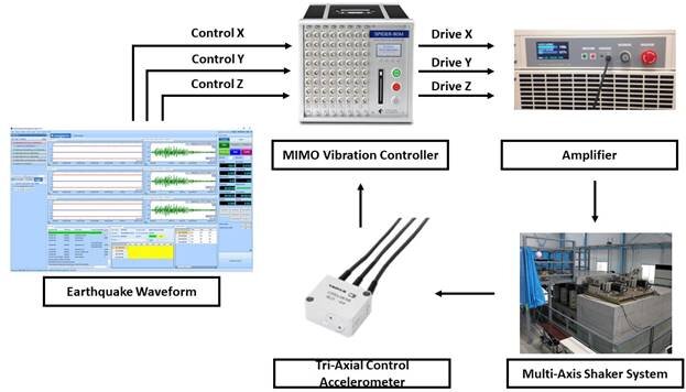
A vibration control test is one of the most reliable ways to carry out this type of dynamic testing. An earthquake profile is programmed into the controller and the shaker table then simulates this movement. It is challenging to accurately represent the earthquake motion. The controller must ensure good control of the low-frequency components which is a significant part of earthquake testing. The hardware configuration is another essential component and the utilization of a three-axis shaker table is an accurate implementation for this type of vibration control testing.
Figure 1. Multi-Axis Earthquake Waveform Vibration Control Test Block Diagram
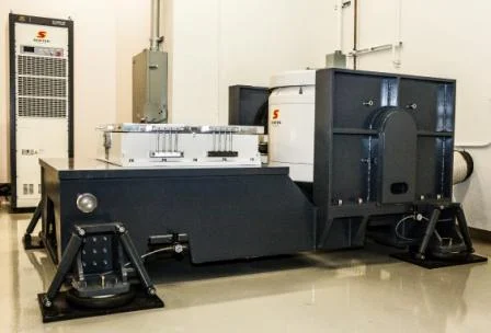
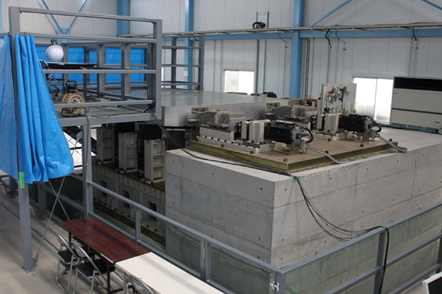
A similar application is discussed here. A three-axis servo shaker by Nissoku Engineering Co., Ltd. (Japan) is used along with a Crystal Instruments’ MIMO (Multiple-Input-Multiple-Output) vibration control system to perform an earthquake test.
Figure 2. Nissoku Engineering Co., Ltd Three-Axis Servo Shaker System
| X - Axis | Y - Axis | Z - Axis | |
|---|---|---|---|
| Force (Sine) | 88.25 kN | 88.25 kN | 117.6 kN |
| Frequency Range (Sine & Random) | 0.1 - 150 Hz | 0.1 - 150 Hz | 0.1 - 150 Hz |
| Maximum Acceleration | 27 m/s2 | 27 m/s | 30 m/s |
| Maximum Velocity | 0.7 m/s | 0.7 m/s | 0.7 m/s |
| Maximum Displacement | 400 mm (p-p) | 400 mm (p-p) | 200 mm (p-p) |
| Maximum Payload | 2000 kg | ||
| Table Size | 2800 mm x 2800 mm | ||
Table 1. Specifications of the Nissoku Engineering Co., Ltd Three-Axis Shaker System
The long stroke length, high force rating, large payload capacity and wide frequency range of the 3-axis shaker system by Nissoku Engineering Co., Ltd. allows for accurate testing of earthquake waveforms. The AS-10 TB tri-axial sensor which has a sensitivity of 98.07 m/s2 sensitivity and a frequency response of DC – 350 Hz is used for this test. Additional details about the sensor are provided in the following table.
| Value | |
|---|---|
| Sensitivity | 98.07 m/s2 |
| Frequency Response | DC - 350 Hz |
| Safe Excitation | 6 V AC or DC |
| Recommended Excitation | 1 to 3V AC or DC |
| Input Resistance | 120 Ω ± 5% |
| Output Resistance | 120 Ω ± 5% |
| Cable | 0.08 mm2 vinyl shielded cable |
Table 2. Specifications of the AS-10TB Sensor
The efficient Spider-80M by Crystal Instruments’ is a dedicated hardware for MIMO vibration control testing applications. This chassis features 8 outputs which is helpful in executing 6-degree of freedom MIMO testing. The MIMO TWR test type available in the EDM MIMO VCS software by Crystal Instruments’ provides precise, real-time, multi-channel control for mimicking earthquake waveforms.
Figure 3. Crystal Instruments Spider-80M MIMO Vibration Controller
Test Details
1. An earthquake waveform with a duration of 31 seconds is run on the 3-axis servo shaker using the MIMO vibration control system.
Figure 4. Earthquake Waveform for MIMO Vibration Control Testing
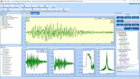
2. The profile is imported into the Crystal Instruments’ EDM Waveform Editor software to fine tune the sampling rate and frame size which helps in better representation and optimized control of this waveform.
Figure 5. EDM Waveform Editor
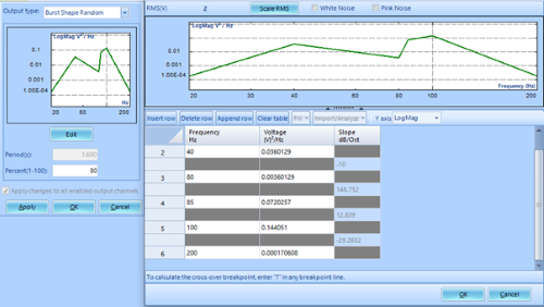
2. Burst Shaped Random setup involves the editing of a PSD (Power Spectral Density) profile and the burst percentage.
Click the Edit button in the output setting and the edit window pops up to allow users to specify the shape of the drive PSD file. In addition, the burst percentage is specified by the user in the edit window.
Figure 6. Output Setting and Edit Window of Burst Shaped Random
Observing the spectrogram, the major components of this earthquake profile are in the lower frequency region.
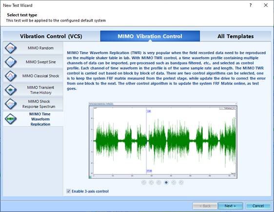
3. The resampled waveform is then imported into the Crystal Instruments’ MIMO TWR (Time Waveform Replication) test of the MIMO VCS software.
Figure 6. EDM MIMO VCS Software
4. The input channel is configured to ensure the setup of multiple control channels. DC Single-End input mode is enabled for controlling the profile down to 0.3 Hz. After the shaker settings are configured and the test parameters are setup, the pre-test is designed accordingly.
The shaped random signal allows the user to tune the level of excitation over the frequency range. This helps improve the signal to noise ratio in the areas where a higher response is desired. This option of customizing the PSD helps in measuring an accurate FRF during the pre-test stage which furthers facilitates better control of the profile during the full-level test.
Figure 7. EDM MIMO TWR Pre-Test
5. The profile exported from EDM Waveform Editor is imported into the EDM MIMO TWR test and the run schedule is set accordingly after checking the profile against the shaker parameters to ensure the safety of running this test.
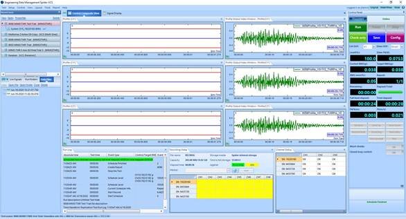
As shown below, the vibration test runs smoothly, and the Crystal Instruments controller and software is successful in controlling the earthquake waveform on the 3-axis servo shaker system.
Figure 8. EDM MIMO TWR Test
The results emphasize the efficiency and reliability of the Crystal Instruments’ MIMO Vibration Control System. To learn more, please visit https://www.crystalinstruments.com/.
