1. Introduction
Multiple-Input Multiple Output (MIMO) Testing has gained a huge momentum in the past decade with the development of multiple shaker table systems, the availability of MIMO vibration control systems, and the readiness of standards (e.g., MIL-STD 810G Method 527, IEST DTE 022 Working Group Recommendation).
In the real world, structural vibrations are excited from sources in all directions. To simulate a real world vibration environment, the testing must be performed simultaneously in more than one direction. Thus, MIMO testing is necessary for many applications. MIMO testing is recommended when SDOF testing is inadequate to properly distribute the vibration energy required to satisfy the specification.
A typical MIMO vibration control system uses a single input channel strategy, with each control channel assigned a profile. This article discusses multiple channel control strategies, which allows users to assign multiple input channels to one control profile. Multiple channel control strategies include the Weighted Average, Maximum, and Minimum.
The nature of these control strategies will be discussed based on the testing results obtained from a three-axis shaker system. Compared to the single channel control strategy, the weighted average control will result in the vibration intensity somehow in between channels for one control profile. Whereas the maximum control strategy will result in the least vibration intensity, since the maximum from multiple input channels is picked to be under control. Opposite to the Maximum control strategy, the Minimum control strategy results in the highest vibration intensity.
With multiple channel control strategies available, the end user can select the correct strategy to test their products under the right vibration intensity to avoid under-testing or over-testing.
2.Testing Setup
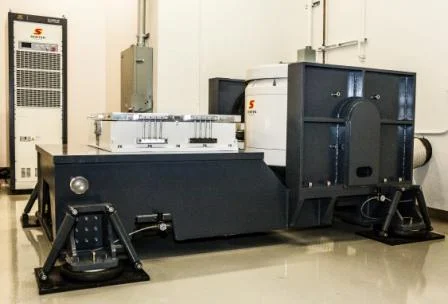
A three-axis shaker table with a head expander is required to carry out tests using different control strategies. The head expander is fixed to one end of the three-axis shaker table. The vibration on the head expander will include the dynamics of the head expander as well.
Figure 1. Three-axis shaker table with head expander
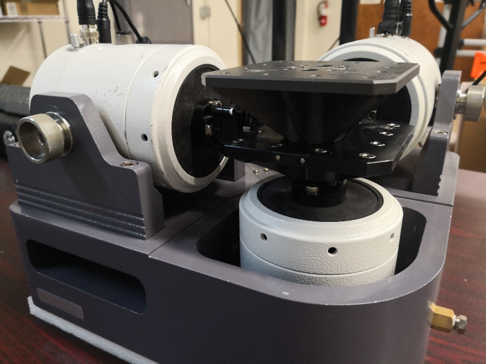
Multiple sensors, including triaxial and uniaxial types are used, as illustrated in the following photo. One triaxial is placed at the center of the three-axis shaker table, while the other is placed on one side. On top of the head-expander, two uniaxial sensors are placed to measure the vibration along the vertical direction.
Figure 2. Sensor arrangement on the shaker table
3. MIMO Random Control
A typical MIMO vibration control system only provides a single channel control strategy, meaning that each control channel is assigned one control profile. This changed recently when Crystal Instruments EDM MIMO Random control started providing single channel control strategy as well as multiple channel control strategies.
The multiple channel control strategies available are: Weighted average; Maximum; Minimum.
Figure 3. Control strategies
The following formulae describes the calculation of the final control signal in the APS format for each type of multiple control strategies.
For weighted average, the control signal can be computed, as
For Maximum Control strategy,
And for Minimum Control strategy,
To compare the control results using above mentioned control strategies, all these control strategies including the single channel strategy will be used to run the MIMO random control on the three-axis shaker table shown in the previous photos.
3.1 Single Channel Control
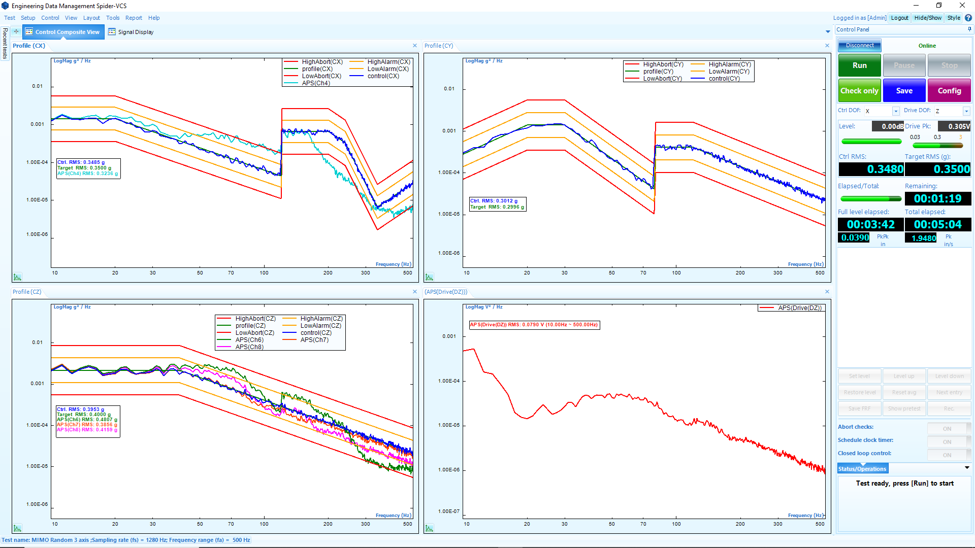
When running the three-axis shaker MIMO Random control, one sensor per each direction is selected as the control channel. The other sensors are enabled to measure the vibration at these locations, as measurement channels only.
Figure 4. Single Channel Control
Users can see that the control works well, and the measurement channel signal illustrates the dynamics of the shaker table and structure on top.
3.2 Weighted Average Control
The control of X direction is the average of two X sensors from both triaxial sensors. The control of Z direction is the average of the Z direction from the two triaxial sensors and two uniaxial sensors on the head expander. When selecting the control channels to be averaged, weight can be assigned to each individual control channel.
Figure 5. Weighted Average Control
As shown in the composite display, each control channel illustrates the vibration of each location, which are up or down versus the averaged control signal.
With this control strategy, the vibration intensity is somehow in the middle of each individual control channel along the vertical direction.
3.3 Maximum Control
With the Maximum Control strategy, the maximum of the X and Z direction control sensors will be the control signal respectively. Since the peak from each individual control channel is chosen, the final control signal can be considered as an envelope of all individual control channel spectrum.
Figure 6. Maximum Control
For this case the vibration intensity would be the lowest, which can be shown by checking the drive signals. Compared to Single Channel Control or the Weighted Average Control strategy, the Maximum Control strategy works well with the lowest drive levels.
3.4 Minimum Control
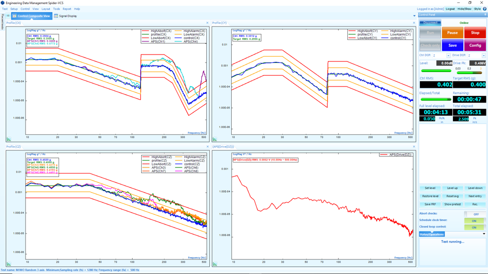
The Minimum Control strategy takes the minimum from the individual control channels. This corresponds to the most vibration intensity among all the different control strategies.
Figure 7. Minimum control
4. Drive Comparison
The following table lists the Z direction drives from each control strategy.
| Control strategy | Z Direction Drive (V pk) |
|---|---|
| Single Channel | 0.305 |
| Weighted Average | 0.283 |
| Maximum | 0.236 |
| Minimum | 0.486 |
Table 1. Z Direction Drive Peak
With Single Channel control, the drive level for the z direction shaker is 0.305 Vpk. This is a typical level since the Z direction control sensor is in the middle of the three-axis shaker table. Users can place more sensors on the three-axis shaker table and on top of the head-expander, which are the locations experiencing higher vibration levels per the dynamics of the system, resulting in the Weighted Average Control strategy requiring a lower drive voltage of 0.283 Vpk.
It is obvious that the drive is the lowest at 0.236 Vpk when Maximum Control is selected. Users can also observe that the Minimum Control requires the highest drive level at 0.486 Vpk.
5. Summary
In this article, multiple channel control strategies for MIMO VCS are studied along with the single channel control strategy. Compared to the single channel control strategy, Weighted Average Control will result in the vibration intensity somehow in between channels for one control profile. The Maximum Control strategy results in the least vibration intensity, since the maximum from multiple input channels is selected to be under control. Opposite to the Maximum Control strategy, the Minimum Control strategy results in the highest vibration intensity.
With the availability of multiple channel control strategies besides the typical single channel control strategy, users can select the correct strategy to test their products under the right vibration intensity to avoid under-testing or over-testing.


